Saturday, 26 March 2016

PCB Fabrication and SMT Assembly - 1

Listed are the few tips for your PCB fabrication and assembly.

CEM-1, CEM-3 as base material for PCB is low cost and not widely used now. this is not used any more. Following are the current material categories for the printed circuit board: 

  • FR4, 
  • High TG FR4, 
  • Halogen Free Material, 
  • Aluminum based material, 
  • Copper based material, 
  • High frequency material,
  • PTFE material
  • Heavy copper foil
  • Paperphenolic plate
  • BT
  • PI
  • Composite material
  • PTFE + metal based
  • Roger HF material

2. When finished copper thickness is equal to or more than 3 OZ, immersion gold as surface treatment is advised.

3. If the solder mask color is white, the PCBA boards may need washing.

Our PCB Tech. has good pre-sale design service and also good after-sale service. Please, do send your queries using below link:
https://ourpcb.wufoo.com/forms/instant-quote-form/

 ----- This post is contributed by Lillian from OurPCB Tech. Ltd

Wednesday, 23 March 2016

Battery charging Basics - 3

In the previous scenario, we have seen battery life time before it must be replaced or before it must be recharged. The condition was that there is a constant current drawn by the load for an hour. In a real time scenario, that is not the case. There will be a sudden current drawn by the load and it remains in sleep for a long period of time. This can be a case in latest IoT (Internet of things) products.

The battery calculations are done this way:

Let us assume, the following conditions for the circuit shown in the previous post:
Switcher output = 1V
Load Current = 1A
So, total power = 1W

For a given efficiency of switcher of 80%, Input power = Output Power/Efficiency = 1/0.8 = 1.25W

For a power of 1.25W at the input, current  = Power/Voltage = 1.25/7.4 = 0.169A

So, in addition, let us assume a condition when the load is drawing current of 0.169A every 10 minutes in a given hour. Considering this scenario, the current of 0.169A will be drawn 7 times an hour and negligible current for the other time.
So, in such case average current drawn by circuit from load is, 0.169*(7/(7+6)) = 0.091A

So, a 7.4V battery with 3200mAh battery capacity supplying 0.091A to load for 1 hour can withstand for, 
3.2/0.091 ~ 35 hours 

The commonly used  terminology here is the duty cycle which is calculated by the formula, TON/ TON+ TOFF


Electromagnetic Compatibility - 2

EMI caused on the board can be radiated as well as conducted. The major reasons are power density, faster switching, higher currents. EMI basically occurs because of unwanted coupling of signals that happen in circuits.

In digital circuits, the interference can be on-board. In these cases we provide isolation between each section in the board to eliminate interference. But if the interference is from external source, we have to use mechanism like EMI filter. The noise is dominant in the higher frequencies and hence a low pass filter can also be used to shutout the noise completely. Other than this as discussed, magnetic component like inductor can also be used. To eliminate noise completely and to handle differential and common mode noise, EMI filter is the best. EMI filter is generally used to eliminate low frequency conducted noise in the circuit where as we use techniques like shielding to eliminate radiated high frequency emissions.

We have to understand that the main cause of conducted emission and hence conducted interference comes from transients, ripple that are generated out of common power supplies. The noise couples over the power path. As we talk about the transients here, which meant sudden change, we can come to a conclusion that we have to use magnetic devices that doesn’t allow sudden change in current.
There are various regulations that define the acceptance levels of this noise. The noise here can be classified into natural and artificial. ESD, lightning come under natural noise sources. The noise emitted from electronic devices come under artificial noise. The conductive emission that we are talking here is an artificial noise.

Natural noise sources - Surge voltages from lighting
Artificial noise sources - switching transients, crosstalk in transmission lines, transients in power supply lines

EMI filter is one of the commonly used passive device for protection against the interference that is generated externally as well as within the device. EMI filter protects the device from conducted interference. We always read through power supply specifications especially SMPS and read that it has an inbuilt EMI filter. This EMI filters suppress common mode as well as differential mode noise. Even though we talk only about supply here there are many instances where EMI filter is used.

The different selection criteria for EMI filter are:
  • Current carrying capability
  •  Impedance
  • Maximum DC resistance
  • Form factor of the filter
  • Capacitance

The various types of EMI filters that can be used for eliminating differential mode noise are:
  • Pi filter
  • T filter
  • L filter

The various types of EMI filters that can be used for eliminating common mode noise are:
  • Common mode choke 

EMI filters are used in the following applications:
  • USB, Ethernet lines
  • AC adaptors
  • Power supply input

The various vendors that supply EMI filters are:
  • TDK
  • MURATA
  • PANASONIC
  • TE
Some of the EMI/EMC standards:
  • CISPR/EN (standard for products used in Europe, Ex: CISPR22, EN55022 which is meant for computing applications)
  •  EN61000 (Ex: EN61000-3-2 for applications < 16A)
  • FCC (standard for products used in US, Ex: FCC part 15 class B which is meant for unintentional radiators)

Friday, 11 March 2016

Battery charging Basics - 2

The main challenge for any system in a battery powered system is the battery withstanding time. For example if you have the following system:


The battery calculations are done this way:

Let us assume, the following conditions for the above circuit:
Switcher output = 1V
Load Current = 1A
So, total power = 1W

For a given efficiency of switcher of 80%, Input power = Output Power/Efficiency = 1/0.8 = 1.25W

For a power of 1.25W at the input, current  = Power/Voltage = 1.25/7.4 = 0.169A

So, a 7.4V battery with 3200mAh battery capacity supplying 0.169A to load can withstand for,

3.2/0.169 ~ 19 hours 

Wednesday, 9 March 2016

USB 3.1 SuperSpeed

We have few personal computers in our houses where they host the USB1.0. The technology has raced ahead and the latest USB standard available is the USB3.1. We all know that USB2.0 works at 480Mbps. But now the USB3.1 works up to 10Gb/s which is called a super speed USB connectivity. We will start seeing PCs and mobiles with these USB3.1 ports in the very near future. USB3.1 basically extends the present existing USB3.0 port standard to a high level, there by almost doubling the speed of the interface. With thunderbolt being implemented on main scale PC devices, at 20Gb/s, USB3.1 speed is comparatively low. there are two versions of USB3.1 stardard named Gen 1 and Gen 2.
Advantages of USB3.1 connectivity:
1. Faster speeds
2. Back ward compatible
3. Power efficient
4. The connector supports 20V/5A for a total of 100W
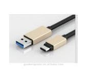
5. Type C cable is used which is easily pluggable

Practical implementations:
1. USB3.1 or any other technology can never achieve the maximum speed it has been designed for. The cables used and their lengths limit the speed of the technology.
2. The processors should be designed to support this new USB3.1 standard.
3. USB3.1 is compatible with USB Type C standard
4. USB3.1 Gen 1 supports 5Gb/s whereas USB3.1 Gen 2 supports 10Gb/s
5. storage devices that require more data and more speeds may implement USB3.1 technology

What is the difference when it comes to USB2.0?

1. USB2.0 has 1 differential pairs with transactions possible in only one direction. Can be said half-duplex.so, there are in total 2 lines for data transmission in USB2.0. where as the USB3.1 standard uses 2 differential signals (1 Tx, 1 Rx) in addition to USB2.0. So, there are in total 6 signal lines in USB3.1.
2. The transactions between host and device can happen in only one direction in USB2.0 where as the data transmission happens in both directions in USB2.0.

Want to buy an evaluation board with USB3.1 included? check the below link:

http://www.asus.com/microsite/mb/best_usb31_solutions/
https://www.asus.com/Motherboards/H170-PRO-USB-3-1/
http://www.asus.com/Motherboards/RAMPAGE_V_EXTREMEU31/

The above link shows a motherboard available from ASUS with USB3.1 connectivity. The RAMPAGE board from ASUS mounts a Intel Core i7 processor on LGA 2011-v3 socket