Monday, 21 September 2015

Signal Integrity : Driver settings

Signal Integrity is a very important concern for any high speed design. The critical design factor lies in how the receiver can analyze the transmitted signal. So, when a signal is transmitted from Driver to Receiver, the transmission path should disturb the signal to least extent. Even the signal that is propagated over the channel between driver and receiver should not interfere with the other signals on the PCB. So, from the driver side, following are the main considerations that need to be taken for a flawless design:


1. Take a proper call on the drive strength that need to be applied from the driver.

The drive strength depends on the load. So, as the load increases, the drive strength must be high. Remember that load is always measured in terms of capacitance. Higher the capacitance more the load. Consider, a scenario where there is a single driver and 2 receivers, the total load can be considered as sum of the load capacitance of the 2 receivers. This can be a scenario with 2 DIMMs connected to a single processor. If sufficient drive strength is not applied from the driver the signal may decay over time and the receiver may not reliably capture the data. Consider a scenario, where the drive strength is too high, the receiver may reliably capture the data in this case but it may cause some other issues like causing unnecessary distortion on the board because of radiation.

Note: Is is always better to use a highest current drive possible from the transmitter but we have to consider that this doesn't affect other routing on the board.

2. Driver impedance versus current

For a design topology between transmitter and receiver has to work reliably, impedance matching between them is the most important thing. So, when you are trying to drive a load, the impedance of the driver is decided by interface voltage divided by current.This gives the output impedance of the driver. So, sometimes when you set the buffer to output specific current, the impedance may have to be matched in your line. So, the requirements and relation of voltage, current and line impedance are to be understood clearly.

3. IBIS models

So, the best way to determine your channel performance is to perform simulations. The simulations are done using best high speed tools available in the market. One of the example is Hyper lynx. there are other tools like Advanced design system (ADS), Sigrity, etc. Choose the tool that you can learn quickly and use it. IBIS model is a file which characterizes the buffer inside your driver. so, check the IBIS model and set your current requirements. 

4. System thresholds

Considering the system thresholds is always a critical factor in determining the performance of your system. Before using the driver and receiver in your system check the VOH,VOL, VIL, VIH and then perform a theoretical calculations to determine if both are compatible. The logic level in a system plays a crucial role. This settings can be done in the ibis model of the driver chipset.

5. Rise time and fall time

The rise time and fall time of the signal propagating between driver and receiver is very important. In the high speed signal theory, the rise time and fall time are critical. The higher the rise time and fall time the faster the signal. For these kind of signal, the slew rate will be high. In the cases where slew rate is too high, there are chances of radiation within the board. So, controlling slew rate is very important.

6. Load current

The load current plays a crucial role. When you power on the system, the load draws a instantaneous current which need to be taken care by the driver. For some interfaces, a pull-up on the line helps to drive the necessary current. But while designing the system the drive setting must be done to accommodate this current.

Friday, 3 April 2015

Design Query

What kind of LEDs should we use for back lighting?

LEDs are of different types - Diffused, Non-diffused, Water Clear, Tinted Clear. For back lighting use only Non-diffused type. non-diffused type helps light concentrate in a narrow beam and make them appear brighter. diffused LED distributes light over wider beam and is not suitable for back lighting.

Thursday, 12 March 2015

Technology: 3D V-NAND

The days of hard disk drives are gone. Solid-state drives are the trend now. Hard disk drives use that spinning technique and used to be slower. The present day drives with solid state devices (transistors) are the popular ones these days. Lot of innovations have been happening around these solid state drives these days. All these innovations run around power consumption, speed and storage capacity (density). Considering the fact that all our laptops run on batteries and in which SSD are popular, power consumption is a primary factor.

To understand NAND memory in detail, a NAND flash ship consists of memory and associated controller. There are players like TOSHIBA, SAMSUNG, MICRON, HYNIX, SANDISK and others. Basically, NAND flash is used to store OS and other user data. This is the memory source for any system. 

V-NAND:

V stands for vertical where the cells are placed vertically. V-NAND uses charge flash trap technology. This ensures larger aerial densities. This v-NAND uses silicon nitride for charge storage and not polycrystalline silicon. The power consumption of of V-NAND will be 50%  of conventional NAND structures. Also, the read/writes are much faster. This V-NAND uses 10nm technology for construction. The reliability of V-NAND is also high. 

3D V-NAND:

This technology is developed by SAMSUNG which increases storage capacity. this technology basically increases the number of layers with the existing space itself enabling increasing densities. This is a kind of layer stacking. Moving ahead to the higher densities this is very useful. 3D V-NAND is a result of intensive research from SAMSUNG. Take a look at the 850 PRO, 850 EVO from Samsung for latest models.

Saturday, 10 January 2015

Standard Commands for Programmable Instruments (SCPI)

An embedded engineer at some stage of his career has to work on complex test and measurement devices. The devices can be a simple multimeter to a complex oscilloscope. There are various vendors for these devices and many of these devices can be tuned as per the requirements. Tuned here meant adjusting the parameters of the test instrument as per the requirement. For example, take an oscilloscope which has some settings to be done before capturing a waveform. Likewise, any test instrument needs an adjustment for usage in real time application. For all these instruments there will be a human interface at the front end and remote interface at the back end. Using both these interfaces settings can be done. Human interface involves display, touch, keypad where as remote interface involves connecting a remote PC using interfaces like GPIB, RS232, Ethernet, USB.
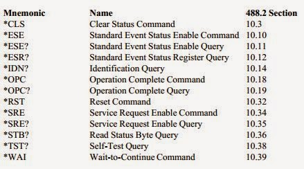
For communicating with instrument from a remote PC/local and to control it some commands are desired which are defined by Standard commands for programmable instruments (SCPI) . IEEE 488 is a standard which talks about the digital interface connections on the test measurements. IEEE 488.1 talks about physical interface. SCPI is an IEEE 488.2 specification. To make command, syntax, formats common across the interface this standard helps. The standard talks about data format and syntax only and never talks about the type of connectivity that exists in practise.

Few snippets from SCPI:
  1. SCPI commands are organized in a tree structure
  2. SCPI is a software standard to communicate between remote PC and instrument
  3. Any instrument from any vendor will use the same standard fro communication
  4. Communication happens by ASCII text strings
  5. The communication can be powering on an instrument, triggering an instrument as in case of oscilloscope, remote calibration, having a view of the instrument from remote, Querying various parameters, etc.
  6. In depth communication is handled by binary formats
  7. Genuine commands like CONFigure, MEASure are some commands which gives a view into what we can expect from the standard.
  8. SCPI is hardware independent
  9. Tests applications like MATLAB, LAB VIEW also support SCPI. MATLAB supports the programming of instruments using SCPI commands through INSTRUMENT CONTROL BOX.
An example of querying DC voltage from a instrument is as follows:

                                                        MEASure:VOLTage:DC?

A look of mandatory IEEE 488.2 commands in the below table:

Monday, 29 December 2014

Numato Labs - One stop for FPGA Development boards/Expansion modules

We have been searching for a platform where we could buy reliable FPGA development boards and finally one day we saw a board in www.numatolabs.com. Without second thought we ordered one board which is suitable for us. We received the board today and till now the response from Numato was exceptional.

Advantages of using boards from Numato:

1. Exceptional support
2. Good technical information regarding the board in the site
3. Chance to raise queries using help@numato.com 
4. Quick and flawless delivery
5. Good follow-up


If we share this information in our blog or share via facebook, we are eligible for a lucky draw. More than trying to win a lucky draw it is everyone's duty to share information which is helpful.

Note: We have been trying very hard to find a vendor who can give reliable evaluation boards and we found one. Thanks Numato!!!

Visit: http://www.numato.com/ for more information.

And finally, have a look at this, use this opportunity to enter lucky draw. Good Luck!!!!
http://www.numato.cc/content/mega-new-year-give-away-2015-grab-your-surprise-gift

Friday, 26 December 2014

Circuit Debugging - Tip 1

Let us start learning some of the debugging techniques. Very common component used in electronics is DIODE. Sometimes, by mistake we tend to connect diode in reverse. So, before, mounting a diode the first thing we have to check is the ANODE and CATHODE. The below symbol indicates the polarities and corresponding representation.


If you still have doubt on the polarity, you can check using multimeter. The below figures shows the same:


Saturday, 6 December 2014

Why use Aluminium for mechanicals?

Have you come across mechanical designs for your projects, then definitely you know that aluminium is the most preferred material for such. There are various reasons  for using aluminium and have a glance at the list below:
  • Good thermal conductor
  • Good electrical conductor
  • Can be shaped easily as per requirement
  • Weighs less, density (mass per volume) is less
  • Durable, soft
  • Resist corrosion
  • Non-magnetic
  • Aluminium is the most abundant metal of all.
  • Gets less affected by environment factors like air and water
  • Doesn't effect the environment, can be recycled
  • Less chances of ignition
The conductivity of Aluminium is 50% of copper but still used widely because of cost factor compared to copper.

Very familiar Applications:
  • Have you seen light poles in your area, they are made of aluminium
  • Electrical grid lines
  • Your kitchen cooking utensils
  • Heat sinks for electronic components and mother boards
  • Bus/car/Rail/Aircraft bodies are made of aluminium
  • Railway tracks
  • Cool drink tins
Note: Aluminium may not be used directly in any application and it is compounds (aluminium + other metals) that are used.