Saturday, 10 January 2015

Standard Commands for Programmable Instruments (SCPI)

An embedded engineer at some stage of his career has to work on complex test and measurement devices. The devices can be a simple multimeter to a complex oscilloscope. There are various vendors for these devices and many of these devices can be tuned as per the requirements. Tuned here meant adjusting the parameters of the test instrument as per the requirement. For example, take an oscilloscope which has some settings to be done before capturing a waveform. Likewise, any test instrument needs an adjustment for usage in real time application. For all these instruments there will be a human interface at the front end and remote interface at the back end. Using both these interfaces settings can be done. Human interface involves display, touch, keypad where as remote interface involves connecting a remote PC using interfaces like GPIB, RS232, Ethernet, USB.
For communicating with instrument from a remote PC/local and to control it some commands are desired which are defined by Standard commands for programmable instruments (SCPI) . IEEE 488 is a standard which talks about the digital interface connections on the test measurements. IEEE 488.1 talks about physical interface. SCPI is an IEEE 488.2 specification. To make command, syntax, formats common across the interface this standard helps. The standard talks about data format and syntax only and never talks about the type of connectivity that exists in practise.

Few snippets from SCPI:
  1. SCPI commands are organized in a tree structure
  2. SCPI is a software standard to communicate between remote PC and instrument
  3. Any instrument from any vendor will use the same standard fro communication
  4. Communication happens by ASCII text strings
  5. The communication can be powering on an instrument, triggering an instrument as in case of oscilloscope, remote calibration, having a view of the instrument from remote, Querying various parameters, etc.
  6. In depth communication is handled by binary formats
  7. Genuine commands like CONFigure, MEASure are some commands which gives a view into what we can expect from the standard.
  8. SCPI is hardware independent
  9. Tests applications like MATLAB, LAB VIEW also support SCPI. MATLAB supports the programming of instruments using SCPI commands through INSTRUMENT CONTROL BOX.
An example of querying DC voltage from a instrument is as follows:

                                                        MEASure:VOLTage:DC?
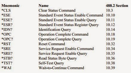
A look of mandatory IEEE 488.2 commands in the below table:

Monday, 29 December 2014

Numato Labs - One stop for FPGA Development boards/Expansion modules

We have been searching for a platform where we could buy reliable FPGA development boards and finally one day we saw a board in www.numatolabs.com. Without second thought we ordered one board which is suitable for us. We received the board today and till now the response from Numato was exceptional.

Advantages of using boards from Numato:

1. Exceptional support
2. Good technical information regarding the board in the site
3. Chance to raise queries using help@numato.com 
4. Quick and flawless delivery
5. Good follow-up


If we share this information in our blog or share via facebook, we are eligible for a lucky draw. More than trying to win a lucky draw it is everyone's duty to share information which is helpful.

Note: We have been trying very hard to find a vendor who can give reliable evaluation boards and we found one. Thanks Numato!!!

Visit: http://www.numato.com/ for more information.

And finally, have a look at this, use this opportunity to enter lucky draw. Good Luck!!!!
http://www.numato.cc/content/mega-new-year-give-away-2015-grab-your-surprise-gift

Friday, 26 December 2014

Circuit Debugging - Tip 1

Let us start learning some of the debugging techniques. Very common component used in electronics is DIODE. Sometimes, by mistake we tend to connect diode in reverse. So, before, mounting a diode the first thing we have to check is the ANODE and CATHODE. The below symbol indicates the polarities and corresponding representation.


If you still have doubt on the polarity, you can check using multimeter. The below figures shows the same:


Saturday, 6 December 2014

Why use Aluminium for mechanicals?

Have you come across mechanical designs for your projects, then definitely you know that aluminium is the most preferred material for such. There are various reasons  for using aluminium and have a glance at the list below:
  • Good thermal conductor
  • Good electrical conductor
  • Can be shaped easily as per requirement
  • Weighs less, density (mass per volume) is less
  • Durable, soft
  • Resist corrosion
  • Non-magnetic
  • Aluminium is the most abundant metal of all.
  • Gets less affected by environment factors like air and water
  • Doesn't effect the environment, can be recycled
  • Less chances of ignition
The conductivity of Aluminium is 50% of copper but still used widely because of cost factor compared to copper.

Very familiar Applications:
  • Have you seen light poles in your area, they are made of aluminium
  • Electrical grid lines
  • Your kitchen cooking utensils
  • Heat sinks for electronic components and mother boards
  • Bus/car/Rail/Aircraft bodies are made of aluminium
  • Railway tracks
  • Cool drink tins
Note: Aluminium may not be used directly in any application and it is compounds (aluminium + other metals) that are used.

Sunday, 2 November 2014

Understanding RS232 interface/signalling - Part 1

Serial port commonly to as RS232 communication is the most widely used interface in embedded systems. Whether it be micro-controller, processor, FPGA the basic interface and the slowest interface that is used is serial port. RS232 communication complies to requirements of EIA/TIA-232 and V.24/V.28 standards. the two main terminologies we come across in these standards are DTE and DCE.

DTE is nothing but an equipment which transmits or receives digital data. This equipment processes the data and converts it into relevant form the users. One of the best examples of DTE is Personal computer (PC). The other examples include printers, fax machines, etc.

DCE is nothing but a simple level converter kind of circuit to make the DTE compatible with communication equipment. Sometimes DCE is a part of DTE and doesn't exist independently. Modems existing in the market are an example of DCE.

The following figure shows the connectivity between DTE and DCE in it's simplest form.


Note: RS232 full form --> Recommended standard-232

Thursday, 30 October 2014

Using crystals in embedded applications - Part 5

What is series resonance and parallel resonance in crystals?

Series resonance crystal does not have any reactive components like capacitor. Parallel resonance crystal is used where there are reactive components involved. Series resonance crystals are resistive in nature where as parallel resonant crystals combine the phase shift properties of reactive components to determine the oscillator frequency. The following circuits explain the difference.

Parallel Resonant circuit

Series Resonant circuit 

In a parallel resonant circuit, load capacitance is a critical specification.Load capacitance is the capacitance which is seen across the terminals of crystal. When we use this crystal in the application, this load capacitance must match the load capacitance requirements of the device to which crystal is connected. 

A same crystal can act as series as well as parallel resonant. When used in an application, the first resonance at which crystal oscillates is the series resonance and later when reactive component like capacitor is added it oscillates at different frequency which is called parallel resonance. So, from this point if i want to use a parallel resonant crystal and we use a series resonant crystal my crystal operates at a higher frequency than desired. In turn, if a parallel resonant crystal is used in place of series resonant requirement, the parallel resonant crystal operates at a lower frequency than specified.

What is the bandwidth of crystal?

The difference between series resonant frequency and parallel resonant frequency is called the bandwidth of the crystal. Lower the bandwidth higher the stability of the crystal. As per the quality factor definition, (Centre Frequency/bandwidth), lower the bandwidth higher the quality of the crystal. So, for your application choose a crystal by checking at the quality factor curve.

What is the crystal equivalent circuit?


In the above circuit,
Co = Holder capacitance (capacitance contributed by leads extending outside the crystal)
L1 = Motional inductance
C1 = Motional Capacitance
R1 = Series resistance

The common term used in crystal specification is hermetically sealed package. What does that mean?

Hermetically sealed meant air tight enclosure with only provision for external connectivity. In our crystals case, the electrodes are extended out.

What is the difference between AT cut and AT strip crystals?

AT cut is the cylindrical version of the crystal and AT cut is the stripped version of cylindrical crystals for miniature crystals.

What constraints can affect the crystal performance?
  • Assume that we connected a crystal in our application, the drive provided to the crystal should not exceed the specifications of crystal. If drive provided exceeds the rating, the crystal life time gets reduced.
  • Temperature at which the crystal is operated
  • Improper load capacitance can vary the crystal frequency from the desired value
What are the fundamental and overtone specification of a crystal?

Fundamental frequency is specified for lower frequency crystals (around 8 MHz, 24 MHz, etc) where as overtone is odd multiple of fundamental frequency. Overtone crystals are not preferred for micro-controller applications.

Tuesday, 28 October 2014

Using crystals in embedded applications - Part 4

Ceramic resonator (vs) Quartz Crystal (vs) RC Oscillator (vs) Silicon Oscillator:
  • Ceramic resonator and quartz crystal are mechanical resonant devices where as oscillator works on electrical phase shift principle (where R-C are the phase shift circuit).
  • Power consumption of Ceramic is more than quartz crystal. 
  • Ceramic resonators have good rise time than quartz crystals.
  • Ceramic resonator and quartz crystal operate on the same principle as the electrical signal applied to them causes mechanical vibrations. 
  • Ceramic resonators are more rugged than crystal.
  • Quartz crystals are very stable and maintain their frequency under extreme conditions. Quartz crystal may not drift from it's frequency even when the PCB stray capacitance is high. Also, at quick varying temperatures, the quartz crystal remains stable.
  • Ceramic resonators are made of ceramic material which are not as stable as quartz. These are piezoelectric in nature.
  • Comparatively, Quartz costs more than ceramic resonators. 
  • Ceramic requires much higher load capacitance required to quartz crystal.
  • An oscillator is addition of feedback to the crystal along with amplification such that oscillations happen. Take the case of micro-controller, on the external clock pins we add a crystal and combined with internal circuitry it forms a oscillator.
  • Oscillator is immune to EMI and humid conditions as they come packaged with all components for frequency generation.
  • Temperature co-efficient which is a important material property is low for crystals and resonators.
  • Ceramic resonators are available in miniature packages also.
  • Ceramic resonator can sometimes be of compound material which helps change the characteristics of the crystal as per the material.
  • The main disadvantages of oscillators is package size and cost and sensitive to vibration,  

Note: Some micro-controllers have internal capacitors, in this case, there is no need to have external capacitors.

Considering the disadvantages of ceramic resonator compared to Quartz, where do they find application?

Check the age old radio circuits you find resonators. Also, they are used in cost critical application and applications where stability is not important criteria.

What is the main selection criteria for any clock input?

Accuracy is the important criteria. Depending on the application for which the circuit is used, clock must be chosen properly. For example, applications like USB, SATA, PCIe requires a very stable clock with less deviation from the desired frequency.

Note: There are R-C oscillators internal to some ics which have very less stability but is a very cheap implementation. Micro-controller internal RC oscillator is an example.