SATA short form for Serial Advanced attachment interface is a serial bus interface for interconnection of storage devices to processor. If you know desktop ingredients, you must be familiar with names like PATA, SCSI, SAS interfaces. PATA short form for Parallel advanced attachment interface has been used in personal computers for connecting hard disk drive to processor. PATA is a parallel interface with up to 40-60 wires (16-bit wide data interface). As we all know the disadvantage with parallel interface is mainly the length of transmission. even though we can achieve higher data rates with parallel interface, the main disadvantage is the length of transmission. with PATA we can achieve only 45-90 cm distance. Also, PATA can work only up to 133 MHz rate and uses +5V for signalling (TTL). The same PATA interface can be shared by many drives but due to bulkiness of connector, sharing not recommended. PATA is also knows as IDE or ATA. Hard disk drives available in the market are of sizes 2.5", 3.5" and 1.8". 3.5" drives are used in desktops and 2.5" drives in net book.
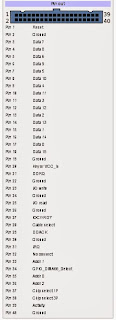
The below figures show PATA connectors, PATA HDD, PATA pin out.
The below figures show PATA connectors, PATA HDD, PATA pin out.
Considering above points, a new interface came into existence which added serial features to SCSI (small computer system interface). It was called SAS short form for Serial attached SCSI. This basically can operate up to 1.5 GB/s and can have cables up to 8 meters long. this was used mainly for servers.
Now-a-days in desktops you don't see SCSI, PATA and SAS. A serial interface standard called SATA is seen. It differs from PATA in many ways and is not compatible in any ways. SATA is basically a serial interface standard which uses LVDS signalling for data transmission. There are various versions of SATA existing now like SATA 1.0, SATA 2.0, SATA 3.0 and SATA 4.0.
Electrical characteristics of SATA interface:
- AC coupling capacitance of SATA is 12 pF
- 100 ohm differential impedance
- NRZ encoding
- 8b/10b encoding
- Transmit Rise/Fall time - 67-273 ps
- 250mV differential LVDS signalling
Mechanical considerations of SATA interface:
- SATA uses 7-pin data connector with appropriate grounding between differential lines
- Uses 15-pin power connector, with staggered spin-up pin support
- Uses +3.3V, +5V, +12V on the connector
- Each pin in the connector carries 1.5 A current
- Six standard ground pins on power connector
- 1.27mm pitch connectors used
- 1 meter length cable supported for SATA
The following figures show pin-outs for SATA power and Data connector
Some of the important points about SATA interface:
- Capacitors on SATA line which are used for DC biasing are placed near to transmitter section
- Hot plug supported in SATA interface
- SATA supports data rates of 1.5 Gbps, 3 Gbps, 6 Gbps and 16 Gbps.
- SATA uses I/O queuing protocol for efficient data transfer
- In the evolution of any standard, to increase reuse of interface level hardware elated to ASIC, PHY, firmware same command will be used from previous versions of that standard. In SATA case also, command set from PATA has been retained.
- If one wants to connect SATA device to a processor which doesn't have native SATA support, adapters are available. For example, if processor supports PATA, adapters can be used to connect SATA drive to processor
- SATA Express is the latest standard of STA which supports up to 16 Gbps, this is done using native PCIe interface of the processor. A Mini PCIe support is enough on the board to connect a SATA express drive to board.
- Observe the pins on SATA connector, you see them arranged in staggered manner. This helps to support hot plugging and improved mating
- Wafer based connectors are used for SATA connectivity
- A pin is reserved on power connector for SATA. This pin named as staggered spin up/activity is used to control drive spin on power up of unit. when staggered pin is pulled down by default, the drive spins as soon as the power is applied. This is little power consuming. Another case where staggered pin is pulled up. In this case, drive starts spinning, only when it is communicated to.
- The mating count of these SATA connectors are restricted to less than 50.
- SATA is half duplex interface
- When SATA is not used, transmit pins float to the common mode voltage level


No comments:
Post a Comment